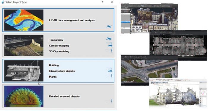
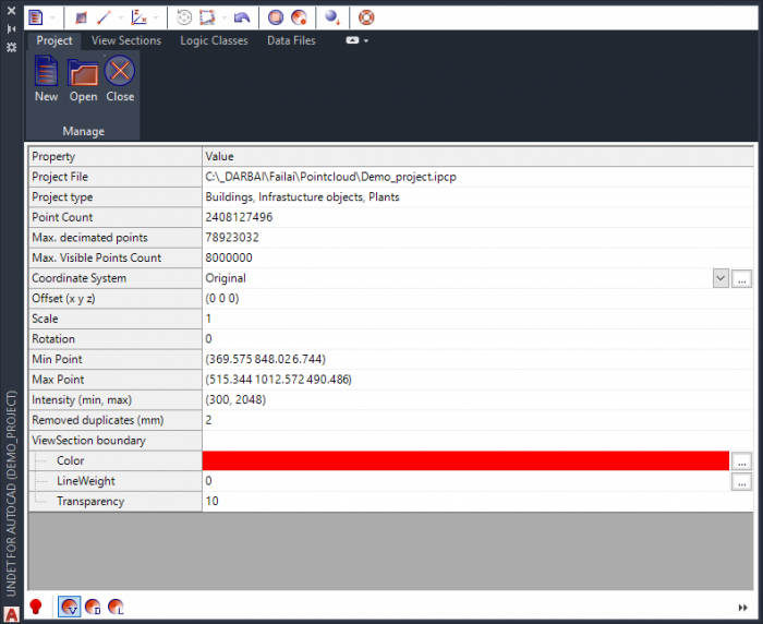
Once you have created a Point cloud project you will use the Undet for AutoCAD plugin to load it into the AutoCAD environment. Once the project is loaded the Project tab will be filled with all sorts of information about the project which will be visible until you close the loaded project.
2D building modeling can be separated into 3 drawings: building elevation, building section and floor plan. Even though a floor plan drawing work flow is slightly different from section and elevation drawing work we will talk about them all at once since the outcome and the target are the same- to draw elements that can be seen in that specific plane.
We created the Undet plug in with our development team according to user needs. So that people will be able to use our software on their preferred CAD software, and with that being said it is safe to say that this plugin was created to improve the user modeling time without changing modeling habits.
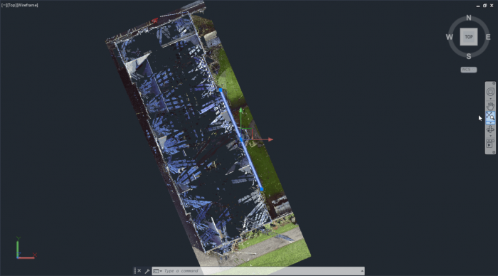
The first step of our suggested super-smooth workflow is to create a correct UCS. You should find the longest building wall and rotate the view by drawing line and using the command view by line from the visibility management tools tab. After this you can create a new UCS that is defined by the current view. At this point you should save the new UCS using the UCSMAN command from the command line. We recommend saving a UCS every time you create a new one.
To make sure that your new UCS is correct, you should draw some perpendicular lines to see if these are parallel with the building walls. You should draw multiple lines and check a couple different walls.
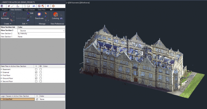
The second step is to create the view section of your area of interest. Here Undet becomes handy once again. Creating and managing view sections in Undet is much easier than performing the same actions with crop areas in the native AutoCAD environment. Every time you create a new view section it will be automatically saved in the view section list. We also created keyboard shortcuts for current view section selection- Ctrl+Shiht+Q and view section grip switching- Ctrl+Shift+1. You can find out more about view section clipping box management here. We recommend creating multiple view sections in the beginning: one for floor view, one for ceiling view, one for section view, etc.
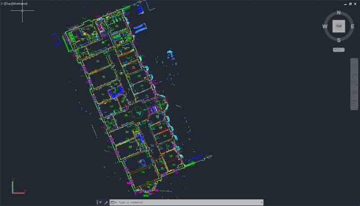
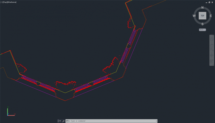
The third step is the main outline drawing. It does not matter if you are working with a section or floor plan drawing, once you have your UCS and view section ready for modeling, you should start from the main outlines.
The forth step is internal wall drawing. This step is almost the same as the previous one, except the fact that now internal scans data will be active in the view section. Once again, by using the UCS that you created you should be able to model walls which will be parallel and perpendicular to each other as long as there are defined tolerance boundaries. Depending on your project, our specialists suggest using 30 mm tolerance.
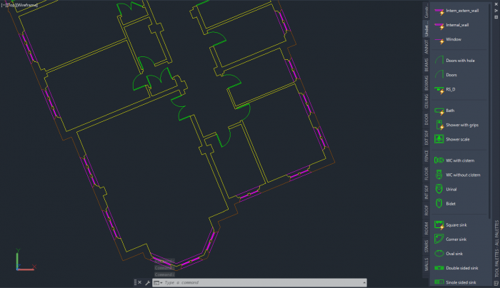
The fifth step is wall element drawing. To simplify, in this step you should draw doors and windows. Using Undet dynamic blocks this step becomes really easy, because you can add doors and windows of any size and orientation by adding the same block everywhere and adjusting the size and orientation using interactive grips.
Detailed view of window profile.
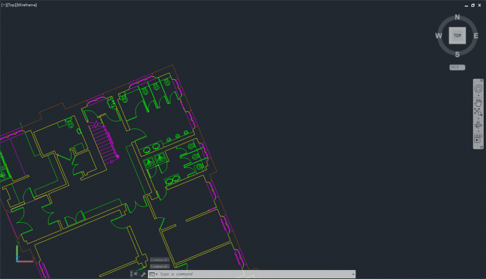
The sixth step will be floor element drawing. In this step you will create a view section in which you will be able to see all floor elements such as stairs, radiators, bathroom and kitchen fittings, furniture and so on. Once again dynamic blocks will be handy. If you are working with elevation drawings in this step you should draw additional facade elements.
The seventh step will be ceiling element drawing. In this step you will create a view section in which you will be able to see all ceiling elements such as sloping ceilings, changes in ceilings, soffits, beams and so on.
In this step we recommend working on one room at the time, because ceiling level values might be different in each room, and if you work with one big view section you might miss some elements.
This step should also include roof element modeling.
The last step will be drawing annotation. This step will be a little bit more complex, because you will have to add different annotations to different objects. Undet also provides dynamic annotations, which will help to save you a lot of time. In this step creating the correctly sized view section will save you a lot of time, because you will be able to move it to different locations and reuse the same one instead of creating a new view section all the time. Annotation value adjusting using multiple view ports is a must while working with annotations, because it saves a lot of time compared to how long it takes to add annotations while using the single view port.
In elevation drawing this step should be the same.

Annotation value adjustment using multiple view ports and dynamic annotation blocks.
As you can see, modeling might be challenging, but if you use our suggested workflow the process of making complete 2D drawings will become super-smooth and easy.